
电风扇电机是电风扇的重要组成部分,其性能参数的好坏很大程度上决定了电风扇产品的质量,因此,很多维修师傅在实际操作过程中都会选择电机作为切入点,然后具体分析相关故障问题。今天就为大家介绍电风扇电机好坏的测量方法以及如何用万用表检测电风扇电机好坏的分步详细解答。
一、怎样测量电风扇电机的好坏
方法如下:电风扇电机有五根线。
分别为:1档,2档,3档,2条电容线。
一般来说,除了个别电机外,三个档位的线颜色是红。蓝。绿。电容是接在黑黄两根线上。启动后,电机的五根线就拆下来了。
1、首先,将万用表的档位调到母档,红表笔接任意一根电容线,黑表笔接1档。
2、先记下电阻值,然后测量2、3档,正常情况下,测量的档位越大,它与电容线之间的电阻值越大,比如1档为70欧姆。2档110欧姆。3档150欧姆等等。
3、你可以记下来然后对比一下。也就是说,如果你测量上面三个档位的阻值都是无穷大,或者某个档位的阻值是无穷大,那就是电机线圈烧毁了或者某个档位的线圈断了。
4、最后一点,测量旁边五条线与电机外壳,也就是所谓的\“地\”有没有短路。
二、怎样用万用表检测电风扇电机的好坏?
五根线都是三速电机的,测试起来比较困难,五根线两对分别测量,首先确保它们是接好的,而且五根线都没有对地短路,找出两根中最大的电阻,两根分别是启动和运转的,然后在两根之间接一个电容,然后从这两条线里面任意一根和剩下三根里面任意一根,通电,看看转向,如果转向正确,那么证明接的电容同时接在通电的那根是运转的,转向不正确,就是另一根是运转的。此时已经知道哪一根是启动和运转的了,剩下三根是公共端,分别对应不同的档位,然后通电试试看。
从理论上讲,公共端与运行端之间的电阻加上公共端与启动端之间的电阻等于启动端与运行端之间的电阻,运行端与公共端之间的电阻大于启动端与公共端之间的电阻。
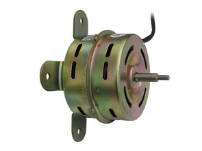
C.电机风扇介绍
电机风扇虽然可靠性高,但毕竟是机械设备,长时间使用会出现转速下降甚至停止的情况,因此最好实时监控风扇的运行状态,以便及时发现问题。使用报警传感器可以在风扇转速低于一定阈值时发出报警信号,而转速信号输出可以实时监控风扇转速。风扇电路输出的报警信号有“高”和“低”两种状态,两种电平代表的含义一般按照正逻辑系统,高电平代表“故障”,“低”代表“故障”,“低”代表“正常”。风扇电路输出的转速信号通常为脉冲形式,每个波头代表风扇转一圈,这种信号可以通过数据总线直接提供给上位机显示。有些风扇输出的转速信号并不是风扇的真实转速,而是转速的倍数,比如每转2个、4个或6个脉冲,这些脉冲要经过处理才能形成风扇的真实转速信号。要判断风扇转速是真实转速还是真实转速的倍数,可以用转速表测出实际转速,然后与显示的数据进行比较。风扇转速信号通常由三根引线插头输出,其中黄色和黑色引线分别接+12V电源和地,另一根彩色线为转速信号输出。需要注意的是,有些三根引线风扇的第三根引线不是转速信号输出线,而是转速控制信号线,转速控制信号通过该线输入到风扇电机。
测量电风扇电机的方法比较简单,不需要我们掌握太多的专业背景知识,只要参照上面的方法步骤和详细操作,相信我们一定可以成功检测。另外,上面我们也对电机风扇的内容进行了分析和介绍。电机风扇作为可靠性极佳的特种风扇,适用于某些有特殊要求的场景。